My local Amateur Radio Emergency Services (ARES) team was encouraged to become proficient using WinLink to exchange email messages between those who need help and those who can provide it. In an emergency, when power, the Internet, landlines, and cell service are down, we learned that the government would have plenty to do without having to help civilians with locating loved ones, pets, or dealing with other, non-life-threatening issues. This is where the ARES team can help. We’re formulating plans to gather messages from the local population, create radiograms, and transmit them outside the affected area by radio where they can be re-transmitted over the Internet or by cellphones.
Communications services are often the first to go in a man-made or natural disaster, even on a minor scale, thus cutting the population off from their loved ones and reliable news sources. To address this need, FEMA and local governments encourage ARES and RACES teams to develop systems for gathering and composing messages to inform recipients about the welfare of individuals and their families. These are typically “Mom, I’m okay. The house is gone, but we’re staying with Aunt Sally in Vancouver, BC. Signed: Bob.” These messages are best transmitted in terse, carefully composed messages that can be handled efficiently over an overcrowded ether, very much like telegrams sent since the early 1900s.
Another point: Not only will the in-disaster-zone population want to tell their friends and family that they’re okay (or not), but they’ll want to know what’s going on in the outside world. Is help coming? Was this disaster the result of a WMD or “just” the cataclysm caused by the Yellowstone Caldera? What is the government telling us to do? Flee or shelter in place? When will power, fuel, water, roads, food, the Internet, and their soap operas be back?
The purpose of this whitepaper is not to explain the details of how VARA transmogrifies text and files to sound and back, but to explain how ham radio operators can set up a radio (specifically the Yaesu FT-991a) and their own computer to run Winlink and use VARA FM to collect, unbundle, and retransmit those messages. Setting up VARA HF is also possible with the FT-991a, but this paper focuses on VARA FM—the VHF/UHF application.
To learn more about Radiograms and RRI forms, click this detailed explanation .

Figure 1: Standard ICS forms for Radiograms & RRI forms.
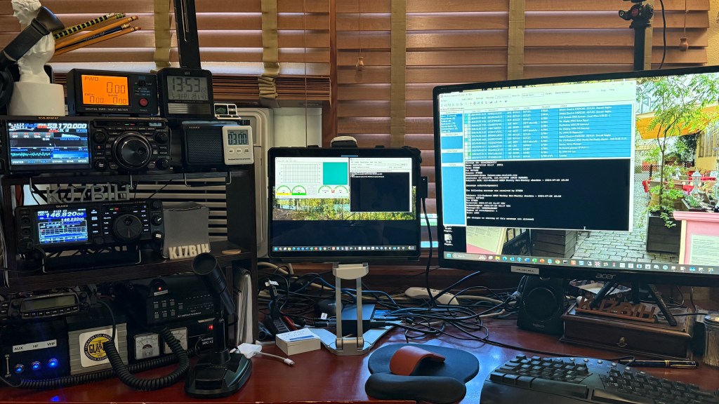
Note: This document guides you through the process of setting up VARA FM on a Yaesu FT-991a and my Surface Pro 9 computer. Your radio, coupled with its unique antenna, and connected to your computer, might pose different hurdles to vault but this document might serve as a guide.
Sending Text by Radio—the Basics of VARA Digital Radio
I learned a great deal from an excellent YouTube video, “VARA Digital on Winlink Express” published by the Burien, Washington ACS and Highline Amateur Radio Club. I recommend that you take the time to watch this at least once, and again after you’ve tried to get VARA FM to work but hit a snag.
Sending text messages over the radio requires a modulator/demodulator (a modem) to convert text and binary to an analog stream of sounds. This burst of tones is transmitted over amateur radio bands to a WinLink gateway system, which takes the analog signal and demodulates it back to text and binary data. At the remote end, that process is reversed to send data back to your computer.
The target gateway system (an antenna, radio, and computer running VARA and Winlink) is identified by a unique callsign and (usually) a suffix as well as a specific frequency, as shown in Figure 2.
Note: Do not assume that all listed gateways are functional 7/24/365. Here in the Seattle area, I found only six of the first forty gateways, as shown in Figure 2, responded to connect requests. But I subsequently learned why gateways are unresponsive. They’re busy, their systems are monitoring several frequencies in rotation, so while it might appear unresponsive, it might take some time for them to get back to the frequency you chose. “Conditions” also impact whether or not a station is usable on the HF bands, but not so much with line-of-sight VHF/UHF gateways.
Ron K04RONTip: A user provided a few suggestions. In the frequency ranges we use here, tuning to a specific frequency might cause the 991a to switch to repeater mode, so you need to eyeball it to make sure you don’t see a [+] or [-] on the dial. If you do, you’ll need to adjust the RPT setting on the M-LIST to “SIMP”. That will also explain why suddenly your monitoring HT isn’t picking up your transmissions.
In addition, he suggests There are also a few settings on the M-LIST whose values and possible settings change based on the Mode, so for example, when setting NAR/WIDE to W 16k, but you can’t until you’ve set Mode to DATA-FM. Conversely, you list setting AGC to Auto, but you cannot do that once you are in DATA-FM. It’s set to FAST and you can’t change it if you’re in DATA-FM mode.
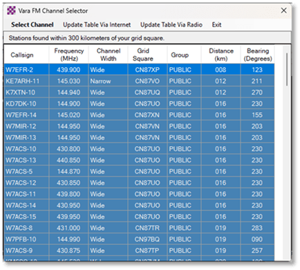
Figure 2: A list of VARA FM Gateways near my QTH.
For VARA FM, these channels are accessed by frequencies in the VHF/UHF bands, so the stations must be in relatively close proximity (in my experience, within 25 kilometers). VHF/UHF connectivity range is generally limited to “line of sight” stations. As hams know, many issues can affect signal clarity, including solar activity, location, mountains, multipath, vegetation, atmospheric issues (QRN), and human interference (QRM). To reach gateways farther away, perhaps hundreds to thousands of miles away, you’ll need VARA HF.
If the gateway is down or not programmed correctly, no amount of pinging will get it to wake up. Unfortunately, until you can identify a reliable (and close) gateway to test against, you’ll be wasting your time experimenting with various radio and VARA settings. Try tuning to the frequency and waiting. If you hear the unmistakable digital handshake sounds, the gateway is functional.
Finding a Gateway
Winlink offers several ways to locate active gateways, such as the Winlink.Org website tools (RMS Channels) as shown below. I checked VARA FM to show only those sites near my QTH. No, I don’t expect to be able to reach clear up to Anacortes or Port Angeles from Redmond, but there are plenty of gateways nearby. Click on the individual green (active) pointer to see the gateway frequency. Note that if a gateway does not respond in two hours, its color changes to yellow, and to red if it cannot be reached in the last four hours.
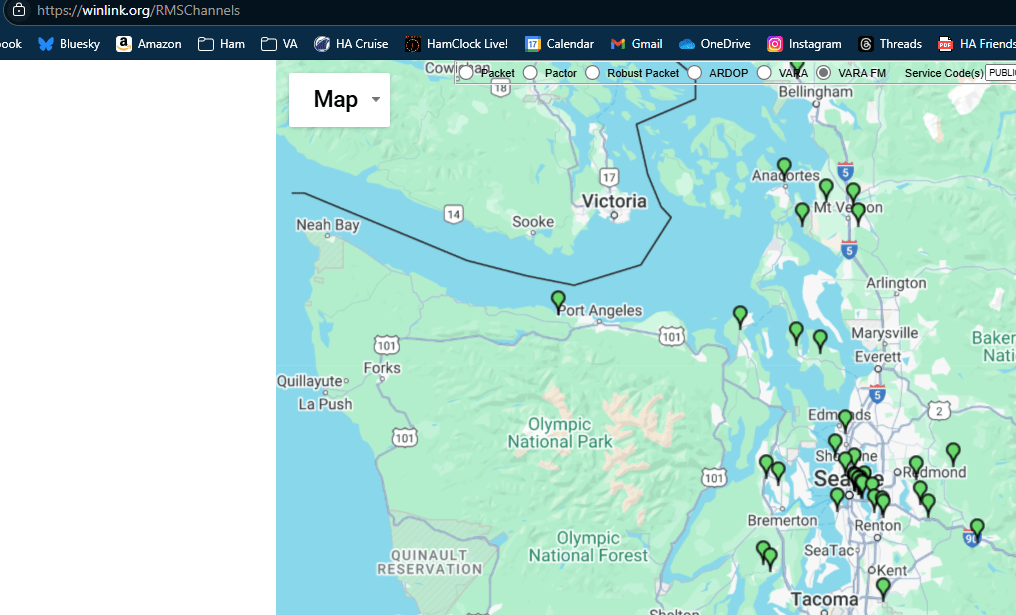
Note: Unlike VARA HF, the VARA FM session manager does not expose this mapping capability.
Configuring the Computer
I use a Surface Pro 9 for my radio work. Yes, that’s overkill. A simple, inexpensive laptop that can run Windows 10 or 11 will do. As VARA will report, the CPU is not pressed that hard during VARA operations. I have the following programs running:
- RT Systems. I use this program to manage the memory channels as well as the option settings for the radio. This way, I can make changes to the radio options (usually through its menus) and upload them to the computer and save them as a working configuration. For VARA FM, this is also where I save the (few) working frequencies to make selecting them easy. No, you can’t communicate with the radio while VARA has latched on to the COM port.
- Yaesu Virtual COM Port drivers. These drivers serve as an essential link between the computer and the FT-991a over a standard “printer” cable that plugs into USB ports on both devices. They appear as Sound and Microphone devices in the Sound driver Settings dialogs. I’ll show how to configure these drivers a bit later. Tip: a friend discovered that his old printer cable did NOT work and spent hours blaming COM port drivers for the issue. Someone (I) suggested he try a different or new (shielded) cable, and that fixed the problem.
Tip: RT Systems software does not program Yaesu’s internal CAT‑control menus (031, 032, 033). Those are radio‑side settings only, and RT Systems communicates with the radio regardless of what memories you program.
✔ What RT Systems does control
Inside the RT Systems application, you set:
- COM port
- Baud rate (usually 38400 or 19200)
- RTS/CTS settings
These settings tell RT Systems how to talk to the radio.
✔ What the radio must match
Your FT‑991A’s Menu 031 – CAT RATE must match the baud rate you select in RT Systems. BUT, if you factory reset the radio (as I have had to do on occasion), it defaults back to 4800 baud even after restoring your other settings. This problem manifests itself as a failure to transmit when starting a VARA FM session.
- Winlink Express. This is the application used to compose messages, pretty much like Outlook or other mail handling apps. I’ll walk through the basics of this app a bit later.
- VARA. These programs, VARA HF and VARA FM, provide the bridge between the COM/USB port and the radio. Basically, it’s a virtual modem that converts data to sound and back again and interacts (to a limited extent) with the radio.
Note: Both Winlink Express and VARA prompt for updates.
I have other programs installed, but none of these are required to run Winlink and VARA. These include:
- Edge: The Windows browser with shortcuts to QRZ.COM to look up the locations of specific gateways.
- SDRUNO: This free program links my RSP1a, a Software Defined Radio (SDR), used to browse the HF bands using a configurable waterfall that’s linked to the radio’s CAT controls.
- OmniRig provides CAT control for both my Dx10 and FT-991a. It permits VARA HF and other programs like SDRUNO to remotely set the desired frequency. It does NOT permit VARA FM to control the radio (or any radio).
- A Device Manager taskbar icon to tune the virtual USB COM ports.
No, VARA FM does not (yet) support CAT control beyond PTT. I talked to the VARA folks, but they don’t seem interested in adding that (important) functionality in my lifetime.
Configuring the COM Ports
Once the Yaesu Virtual COM Port drivers have been installed (Yaesu provides copious directions on how to do so), they appear in Device Manager as shown in Figure 3Figure 1.
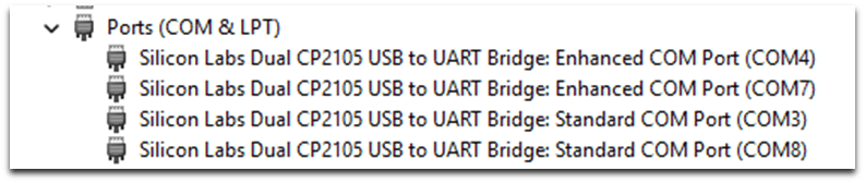
Figure 3: Yaesu Standard and Enhanced USB ports.
Note: This baud rate must also match the Communications Port settings in RTSystems used to interact with the FT-991a settings as well as the baud rate set in VARA FM PTT settings.
Figure 3 also shows there is a second USB cable plugged in to control my Dx10 used by VARA HF. These Yaesu Silicon Labs COM device drivers are installed and managed in pairs. Note that the “Enhanced” ports (COM4 and COM7) are chosen when selecting ports in VARA FM and VARA HF respectively. No, these COM ports do NOT appear in Device Manager when the radio is turned off, however, their configurations settings persist between computer reboots, assuming you don’t plug the USB cable into another one of the computer’s USB ports. If you do move the cable, the port numbers might change, and custom configuration settings might be lost, breaking VARA or RT Systems.
Tip: If you get a driver error when plugging in your USB “printer” cable, note that we’ve found that not all cables are equal in functionality. Try another or borrow one that works to verify it before spending hours cursing at the drivers.
The baud rate of these ports must match the FT-991a 031 CAT RATE setting. It defaults to 9600bps. I use 38400bps on both the Enhanced and Standard ports as well as the radio to improve the performance—mostly of RT Systems.
To set the baud (bits per second) rate, right-click each of the Enhanced COM ports and select Properties | Port Settings as shown in Figure 4.
Note: CAT rate has nothing to do with the speed data is transmitted through the antenna, just the USB cable.
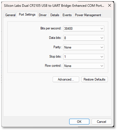
Figure 4: Device Manager COM Port Settings
While you have this dialog open, open the Power Management tab to disable power management for the port, as shown in Figure 5. Press OK to commit these changes.
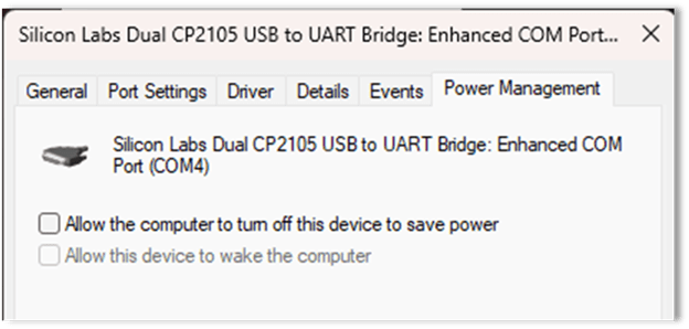
Figure 5: Disable device power management.
Using Windows Settings to Configure COM Ports
Once the USB drivers have been installed and configured, you’ll need to tune them to accommodate VARA—both VARA FM and VARA HF. When two or more radios are controlled by USB ports, knowing which port is connected to which radio is a challenge. To deal with this, rename each port to indicate which radio’s USB cable is being addressed.
Note: You can still have Windows sound play from one port and have VARA or RT Systems connected to another. But, when you are connected to VARA, you cannot share that COM port with RT Systems. You’ll have to shut down VARA while interacting with the radio with RT Systems.
Configuring Sound Ports with Windows Settings
To configure the ports in Windows, open Settings | Sound dialog. As a shortcut, right-click on the speaker icon on the Windows taskbar (lower right corner) as shown in Figure 6.

Figure 6: Windows task bar sound icon
The System Sound dialog, as shown in Figure 7, shows the default speaker device is Surface Doc Speakers which handles Windows-sourced sounds. That need not change.
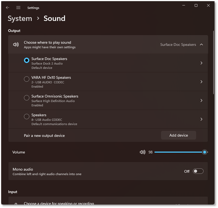
Figure 7: Settings | System Sound
The System Sound dialog also shows the other “devices” installed that can be used to route sounds through the COM port and USB cable and passed on to VARA. Note that the VARA HF Dx10 Speakers device has already been renamed.
To rename the VARA FM device (currently named “Speakers”), open the Properties dialog by clicking on the ‘>’ at the right end of the dialog. Do NOT click on the center part of the “Speakers” dialog as it sets the selected device as the system default. If your computer stops playing sounds, come back here and recheck this setting.
Note that the name generated by Windows (8- USB Audio CODEC) to label the device includes the COM port number (8) as originally set when the device driver was first added. Ignore this number.

Figure 8: Renaming device ‘Speaker.’
Use the Rename dialog to label the Speaker device to reflect that this USB port device is communicating to a cable connected to the FT-991a. Click Rename to commit that change.
When you return to the dialog in Figure 7, scroll down to the Volume slider and set it to 34. This is not a fixed setting, as your computer and VARA might ask to set it to a higher or lower level. We’ll talk about this later.

Next, scroll down to Advanced Settings. Click on Device Default Effects and choose ‘Off’ to disable these sound enhancements as shown in Figure 9.
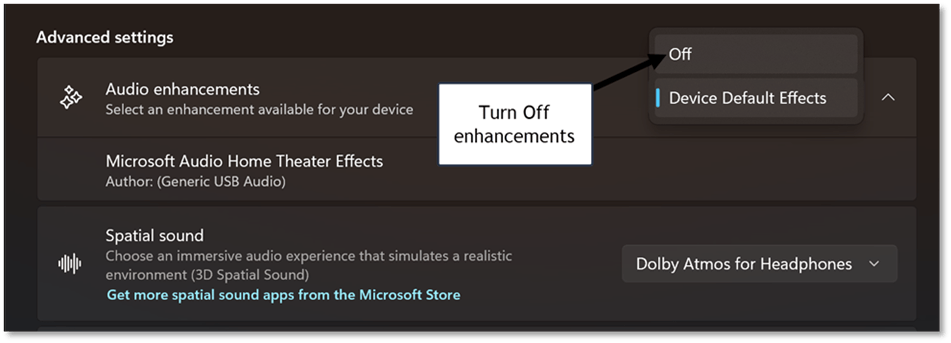
Figure 9: Disable Audio Enhancements
No, you’re still not done with the Sound settings dialog. Navigate up one level back to the Figure 7 dialog. Scroll down to the “Input” section and rename the “Microphone” device added when you installed the Yaesu COM drivers, as shown in Figure 10.
Set the Input Volume to about 1/3 volume, as shown in Figure 10. This is not a fixed setting, as your computer and VARA might ask to set it to a higher or lower level. We’ll talk about this later. Setting these levels now can help give VARA a good chance to generate suitable handshake tones as you try to connect to a gateway.
Note: Setting these audio levels is important. If the speakers are too loud or the microphone is too sensitive, the audio hardware will produce distorted sounds that cannot be deciphered by VARA or the gateway, even if it’s working. If they are not loud enough or sensitive enough, the audio might not be heard.
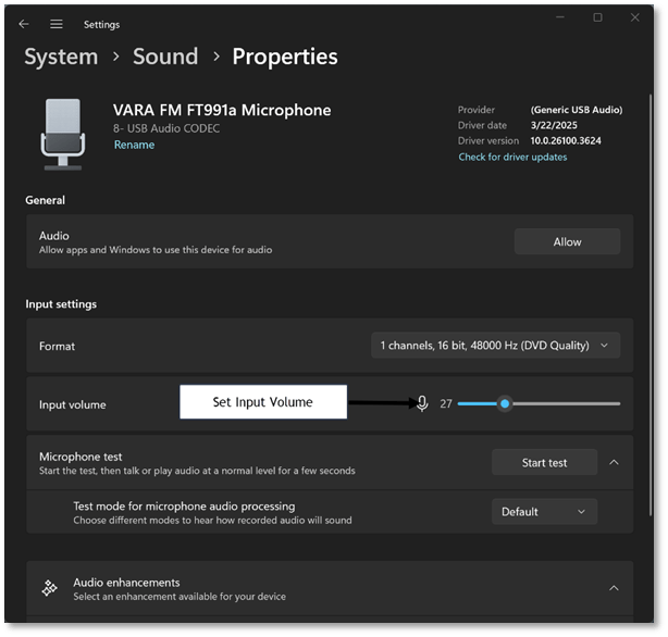
Figure 10: Configure the Microphone
Take a moment to test your computer’s speakers and the microphone to ensure you haven’t changed the default settings. If you can’t hear the sound, recheck the default Speaker settings.
Note: If you accidentally click the Audio “Allow” button, you might disable the port so it won’t appear in any applications like VARA. To reenable the device, scroll down to “Advanced” and click “All Sound Devices”, find the missing device, and reenable it.
Note: If you unplug the USB cable and plug it into another USB port on the computer, all of these settings will be lost and must be reset from scratch.
Configuring the FT-991a
These are several YouTube videos and whitepapers that walk through configuring the FT-991a to work with VARA. Table 1 shows the Menu | Setup option settings for VARA FM. Note that only the (*) items need to be changed.
Note: I expect these settings will also work on the FT-991 (no a).
| Option | Purpose | Value | Notes |
| 031* | CAT RATE | 38400bps | Used by VARA FM for PTT |
| 070 | DATA IN SELECT | REAR | Sound sourced through USB cable |
| 071 | DATA PTT SELECT | DAKY | Used by VARA FM/HF |
| 072* | DATA PORT SELECT | USB | 1200 Narrow only |
| 073 | DATA OUT LEVEL | 50 | |
| 074 | FM MIC SELECT | REAR | (Reset to use microphone in DATA-FM) |
| 075 | FM OUT LEVEL | 80 | 9600bps mode only |
| 076 | FM PTT SELECT | DAKY | Sets PTT for FM modes |
| 077* | FM PKT PORT SELECT | USB | Selects input jack for FM packet signal |
| 078* | FM PKT TX GAIN | 90-100 | Sets transmission gain for FM packet sig. |
| 079 | FM PKT MODE | 1200 | Sets baud rate for FM packet signal. |
| * | (Not default setting) |
Table 1: Menu | Setup option settings for VARA FM
Other FT-991a Settings
All of these settings are made on the front touch-screen, except for MODE* which is set with the MODE button on the front panel.
| Setting Name | Value | Notes |
| NAR/WIDE | WIDE W 16K | |
| AGC | AUTO | |
| MONI | OFF | Not available in VARA FM |
| WIDTH | 3000 | |
| ALL FILTERS | OFF | (All disabled) |
| SQL (Squelch) | 0 | |
| METER | ALC | |
| RF POWER | 20-50 | Start low and work up |
| MODE* | DATA-FM | Set with MODE button. |
The MONI function does not work in FM-DATA. Set up another radio, even an HT, to monitor the data being transmitted by the FT-991a during the connection. I programmed a second radio with the same channel numbers as those set in the FT-991a’s memory.
AF GAIN as needed.
LOCK – to prevent changes to the frequency while configuring radio.
Tip: Back up this configuration including menu settings in RT Systems and label the file to reflect it’s for VARA FM. This makes it easy to revert to “normal” or “VARA HF” settings as need arises.
Installing Winlink Express
It’s beyond the scope of this document to explain how to install Winlink Express—here is one installation guide, and here is another.
You’ll need a valid ham license and a Winlink account, which is created from the Winlink website. Winlink runs on Windows and other operating systems.
Note that Windows 11 will complain that this application is not safe. Click on More Information and Install anyway.
By default, Winlink Express will be installed in the C:\RMS Express folder. Click the checkbox to create a Desktop shortcut and start the app, which will automatically update the Winlink Standard Forms (it does this quite often) and the app itself from time to time.
Configuring Winlink Express
When first using Winlink, click on Settings to fill in your Winlink Callsign, Password, recovery email, and grid square. These settings are persisted in the cloud by Winlink.org and will repopulate in the app based on these saved settings. Fill in your registration key and grid square if not already set as shown in Figure 11. Click Update to commit these changes and save the data to the Winlink server.
Note: Winlink Express accounts age out after 400 days of inactivity.
After that, the accounts are purged.
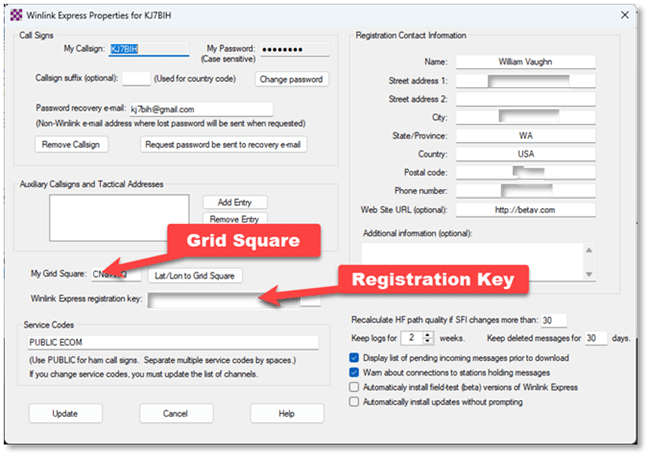
Figure 11: Winlink Express Settings
Installing VARA FM
VARA FM (or VARA HF) is not included in the Winlink installation. Navigate to downloads.winlink.org – /VARA Products/ and choose the VARA FM installer as shown in Figure 12 and click on the .zip file.
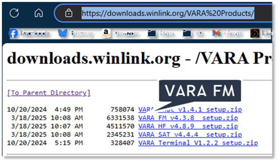
Figure 12: VARA FM downloads link
Note: The VARA FM Setup app is not recognized as a safe application so you’ll have to click on More information and then Install Anyway to get it to launch.
Once VARA FM is first started, it will display outside the context of a Winlink session as shown in Figure 13. Close the VARA FM window. Note the VU meter indicates audio is not reaching VARA FM. This might also be caused by not setting the FT-991a squelch to 0. The VU meter provides a lot of information. If it’s not pointing to the notch just above the red on the right, something in the sound settings on your computer is wrong. Too high? Back off on the microphone gain. Too low? Increase it and make sure the 991a squelch is set to 0.
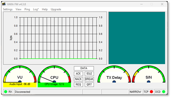
Figure 13: VARA FM when first started.
Next, in Winlink Express, click on the drop-down list to the right of Open Session and choose VARA FM Winlink to select a VARA FM session. Click Open Session to launch VARA FM as shown in Figure 14. This VARA FM session is now linked to Winlink.
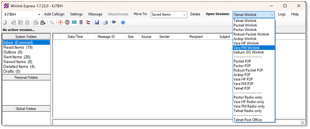
Figure 14: Selecting VARA FM Session
Note that you can also use VARA FM to connect peer-to-peer by selecting VARA FM P2P.
Connecting to a VARA Gateway
At this point, you have three windows open:
- Winlink is used to choose message templates and compose your messages, and select and start an appropriate Session by type (like Telnet Winlink or VARA FM) as shown in Figure 14.
- The VARA FM Winlink Session. This window, as shown in Figure 13, manages the interaction with a selected gateway through the VARA FM TNC. It exposes a list of known (although not necessarily functional) gateways based on the distance from your location. It immediately launches and links with the VARA FM virtual modem (TNC) and checks your registration.
- The VARA FM TNC. This window is used to select the Speaker (computer output) and Microphone (computer input) devices as well as calibrate the system settings. It also displays information about data transfer once a connection has been established.
Configuring the VARA FM Winlink Session
On first use, you’ll need to configure the VARA FM Winlink session. Click on Settings in the Winlink session to first verify the configuration of the VARA TNC, as shown in Figure 15. No changes are needed, so simply click “Cancel.”

Figure 15: VARA FM Winlink Setup Options
Configuring the VARA FM TNC
Click on Settings in the TNC window. This opens a sub-menu with three options as shown in Figure 16.
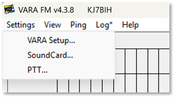
Figure 16: VARA FM TNC Setup Options
Click on VARA Setup. This opens the dialog as shown in Figure 17.
Note that the FM System is set to WIDE. We discuss using the WIDE option with the 991a in a later section. While much of the doc insists that you need to set this to NARROW, virtually all of the gateways here are WIDE, so I just set it to wide and have not seen any adverse effects. Your mileage may vary.
Set Retries to 10. Ignore the cable diagrams shown at the bottom. They are only used to configure use of WIDE transmission mode and the RTTY/DATA port on the FT-991a. Press Close to commit any changes.
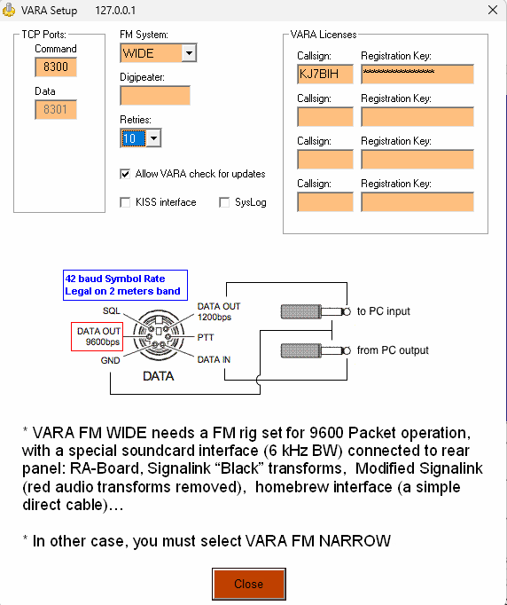
Figure 17: VARA TNC Setup
Configure TNC Sound Cards
Next, click SoundCard… on the menu shown in Figure 16. This displays the current Sound Card configuration as we have discussed before. Ensure that the correct Device Input (Microphone) and Device Output (Speaker) are selected as shown in Figure 18. The “device” mentioned is your computer. Note that these are set to the renamed Microphone and Speaker devices exposed by the USB device drivers. Press Close to commit any changes. We’ll discuss Drive Level, Auto Tune, and Tune a bit later.
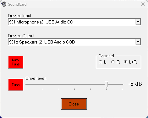
Figure 18: Sound Card device configuration
Configuring Push to Talk (PTT)
VARA FM needs access to the COM port to trigger PTT so the radio can transmit the generated tones to the gateway. Click on PTT… as shown in Figure 16.
Select the same enhanced COM Port used when configuring the Speaker | Microphone devices. Choose “FT-991” from the menu and set the Baud dropdown to the 031 CAT RATE setting in the FT-991a, as shown in Table 1. Check RTS but not DTS as shown in Figure 19. Click Close to commit these settings.
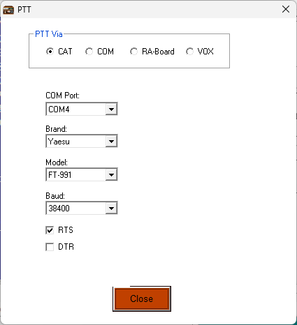
Figure 19: Configuring PTT dialog
Once you configure VARA FM, you’ll see these newly named devices appear in the Settings | Sound Card Device Input dropdown dialogs as shown in Figure 20 and Figure 21.

Figure 20: VARA FM Settings
Note: The names you chose for your sound devices in Windows might include the erroneous port numbers. Remember to ignore this value. Because the other ports used for the VARA HF configuration were renamed, they’re easy to differentiate when choosing the right port.
Note: Once these SoundCard settings are made in VARA, the application remembers them between uses.
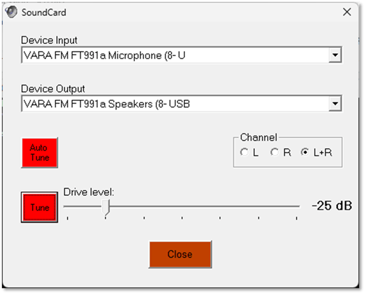
Figure 21: VARA SoundCard selection
Testing the Selected Gateway
Once the configuration options in Winlink and VARA FM have been completed, it’s time to test a selected gateway. We’ll ask VARA FM to display a list of local gateways, and once one is selected, we’ll ask the VARA FM TNC to test it using the Ping command.
Select a Gateway
To choose a Winlink gateway, click on the Channel Selection menu in the Winlink VARA FM Session window. This exposes the list of gateways sorted by range from your QTH, as shown in Figure 22.
Note: Not all gateways are active. Choose one nearby and in a direction not blocked by a mountain or 70-story office building. Remember that Winlink has already been configured to your location grid square. In some “conditions” (sunspots, atmospherics, or your neighbor’s Christmas lights) a poor Signal to Noise ratio might preclude some operations.
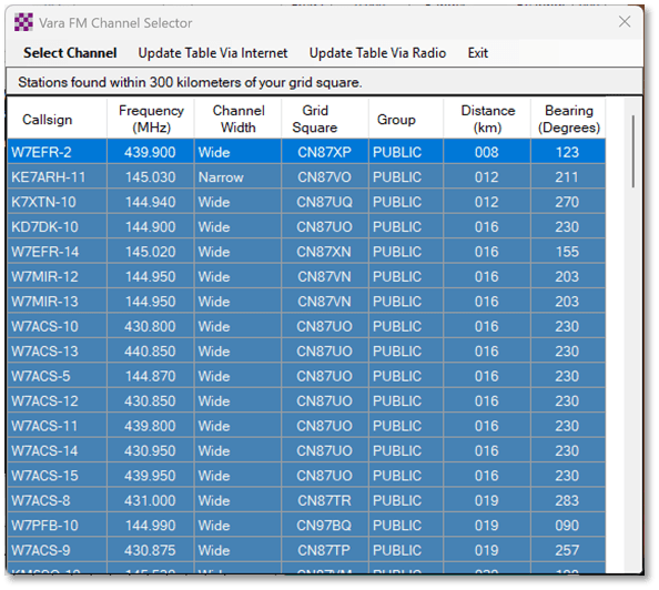
Figure 22: Channel Selection dialog
Once selected, the chosen frequency and callsign are set in the Session window as shown in Figure 23. If this connection works, click Add to favorites to have VARA FM remember this as a working gateway. Keep notes as to the callsigns and frequencies of working gateways to add them to your FT-991a’s memory.
Note: A fellow ham (KO4RON) advised in the frequency ranges near him, tuning might cause the FT991a to switch to repeater mode, so you need to eyeball it to make sure you don’t see a [+] or [-] on the dial indicating an automatic offset. If you do, you’ll need to adjust the RPT setting on the M-LIST to “SIMP” to choose simplex mode.
Other M-LIST settings change based on the Mode. For example, you list setting NAR/WIDE to W 16k, but you can’t until you’ve set Mode to DATA-FM. Conversely, you list setting AGC to Auto, but you cannot do that once you are in DATA-FM. It’s set to FAST, and you can’t change it if you’re in DATA-FM mode.
Next, tune the FT-991a and the monitor radio to this frequency.
Note: VARA FM does NOT set the frequency you’ve selected on the FT-991a or the Monitor radio. These must be set manually. Transmitting VARA FM handshaking on the local ham club’s repeater is sub-optimal. 😉
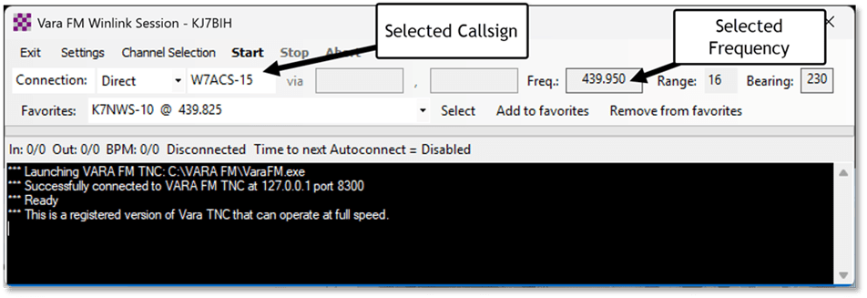
Figure 23: VARA FM Session with frequency selected.
To test this gateway, return to the VARA FM TNC dialog as shown in Figure 24 and click “Ping.” This opens the Ping dialog as shown in Figure 25. This tests the mechanism configured to connect the computer to the USB cable and the radio. Note the gateway callsign might be preset, but if it’s not, enter the correct gateway callsign.
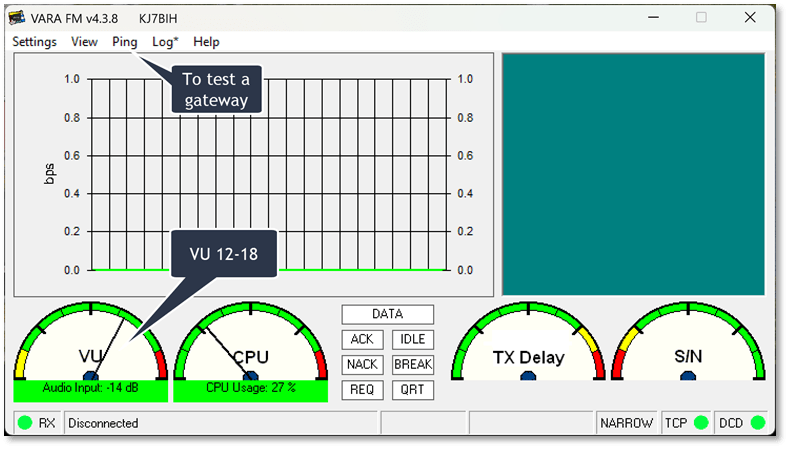
Figure 24: VARA FM TNC ready to Ping
Before testing, make sure the FT-991a AF GAIN control is turned up high enough to hear the static. Remember, your squelch should be set to 0. Also, make sure your “monitor” radio is set to this same frequency, and its volume is turned up a bit.
To test a gateway on the frequency set on the FT-991a, click the “Plug” icon to begin the ping operation.
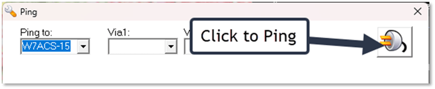
Figure 25: The Ping dialog
If the gateway answers, it will test the connection and, a few seconds later, provide a signal report as shown in Figure 26. If it fails to connect, you’ll get the dreaded “NO SIGNAL” dialog as shown in Figure 27.
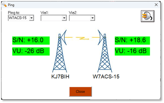
Figure 26: A successful Ping test
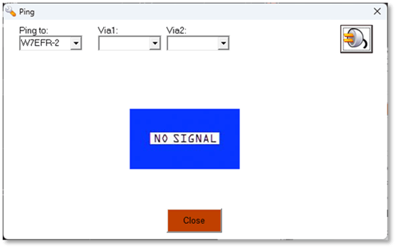
Figure 27: A Failed Ping Test
Some mentors advise ignoring NO SIGNAL dialogs and just starting a session anyway (when the frequency sounds clear). VARA listens to the incoming signal and initially blocks an attempt to connect if it thinks the gateway is busy. You can override this block, but it’s not advisable. To debug a NO SIGNAL dialog, take the following steps:
- Try another gateway. If you hear the handshake tones on the frequency, it’s working, so suspect something is wrong on your end. Listen to the signal on the radio. Is the QRM high on that frequency?
- Re-verify the COM port settings. Remember, reinstalling the COM drivers or moving the USB cables means starting the configuration process from the top.
- Ensure that the Microphone (COM USB) enhancements are OFF and the level settings are mid-range or lower.
- In Windows Sound Settings, set the volume slider on your FT-991 Microphone device so that the VARA VU ~ -14db (1 o’clock) as shown in Figure 28. You should be able to see the VU meter move as you adjust the microphone sensitivity level.
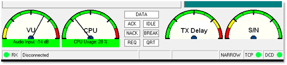
Figure 28: VARA FM TNC gauges
- Ensure the Speaker (COM USB) enhancements are off, and the volume is set mid-range. Auto Tune provides guidance. VARA can compensate for low or high speaker volume within limits. I show how this is done a bit later.
- Tip: If the VU meter is pegged in the yellow on the left, make sure your squelch setting is set to 0. The AF GAIN can be set to 0 as well unless you like listening to the handshake. I prefer to leave it set to a low level (about 9 o’clock) to hear when the connection is working.
- Ensure FT-991a MODE set to DATA-FM.
Note: During testing, MODE switched to FM mode on its own, probably because my RT Systems programming did not specify PKT-FM.
Using Auto Tune to Calibrate a Connection
The VARA FM TNC can help find the ideal drive level to get the best throughput by transmitting a series of ten pings at increasing drive levels. I found Auto Tune did the most good after I had established a good Ping on a gateway. It also showed me that my initial drive levels were set too high for a quality connection.
When using Auto Tune, ensure the FT-991a is set to the right frequency.
To use Auto Tune, open the VARA TNC Settings | Sound Card dialog as shown in Figure 21. Again, ensure that the FT-991a and the Monitor radio are both set to the gateway frequency and click Auto Tune. This opens the Drive Level Calibration window. Ensure the correct callsign and suffix are set in the Calibrate with: dropdown as shown in Figure 29.
Press the “Plug” icon to begin calibration. During the calibration, the TNC displays a countdown of each test. Each test increases the volume of the sounds transmitted to the gateway. When all ten tests are completed, the gateway determines the one with optimal clarity—if any.
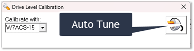
Figure 29: Auto Tune Drive Level Calibration
If the TNC’s attempt at calibration fails, it directs the user to reset the audio level and provides a link to the Control Panel Speaker Properties to adjust it as shown in Figure 30. Make the adjustments and try again.
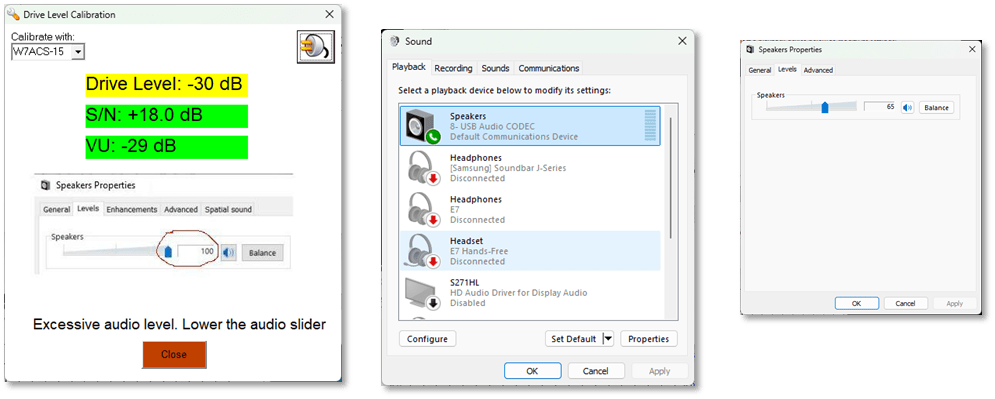
Figure 30: Auto Tune Calibration Fails
Once the drive level is set close enough, the Auto Tune calibration succeeds and the TNC sets the SoundCard drive level for this gateway as shown in Figure 31.

Figure 31: Drive Level calibration succeeds.
Other Tips
- Radio volume during VARA operations is irrelevant.
- Radio squelch should be 0.
- The Windows 11 speaker and microphone settings can still be set to the usual internal settings.
Programming FT-991a Memories
If you’re just getting started, you won’t know which frequencies and callsigns to save in the FT-991a memory channels. However, once you’ve found several working gateways, program them into the radio using RT Systems. Ensure these channels are set to Simplex, with no Tone and with Operating Mode set to PKT-FM (which maps to DATA FM on the FT-991a). Name each channel so it can be easily selected to match the gateway callsign and suffix in VARA. The result is shown in Figure 32. Copy and paste these channels to the Monitor radio so the same channel numbers and names can be easily set. The monitor is not needed except to listen to the handshake tones.
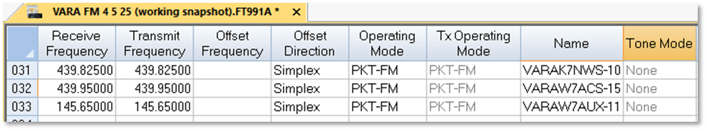
Figure 32: RT Systems FT-991a VARA FM memory settings

You must be logged in to post a comment.